What Is a Direct Drive Linear Motor?
What Is a Direct Drive Linear Motor?
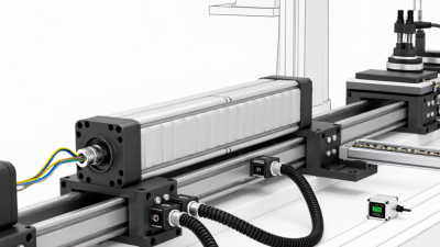
A direct drive linear motor converts electrical energy into straight-line motion without screws, belts, gears, or other mechanical transmission parts. Its force-producing components act directly on the moving load. This design can deliver rapid acceleration, precise positioning, and smooth travel in demanding automation systems. Think of a semiconductor stage moving across a granite surface, or a packaging axis stopping within micrometers. The motion feels immediate. That is the core idea.
Engineers usually describe a direct drive linear motor through its stator, forcer, magnetic circuit, feedback device, and control amplifier. Permanent magnets create the working field, while controlled current produces thrust along the motor’s path. A linear encoder reports position, often with nanometer-level resolution in specialized equipment. Performance still depends on alignment, thermal management, load mass, cable routing, and tuning. The motor alone does not guarantee accuracy.
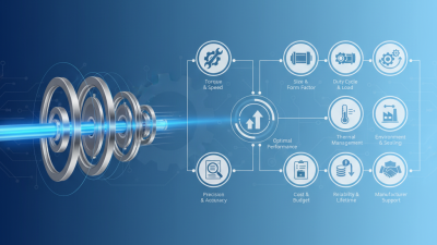
Real-world selection requires measured judgment. A factory engineer should compare continuous force, peak force, stroke length, duty cycle, cooling method, and environmental conditions. Dust, vibration, and heat can change results. Direct drive systems may reduce backlash and maintenance, yet they can cost more and demand careful installation. They also expose a common misunderstanding: faster motion is not always better production. Stability, settling time, and repeatability may matter more. Specifications can look impressive. Application testing remains essential. This guide explains the structure, operating principle, benefits, limitations, and selection criteria of a direct drive linear motor, using practical engineering context rather than idealized claims. Some designs still require compromises.
Definition and Core Principle of a Direct Drive Linear Motor
What Is a Direct Drive Linear Motor?
Definition and Core Principle of a Direct Drive Linear Motor
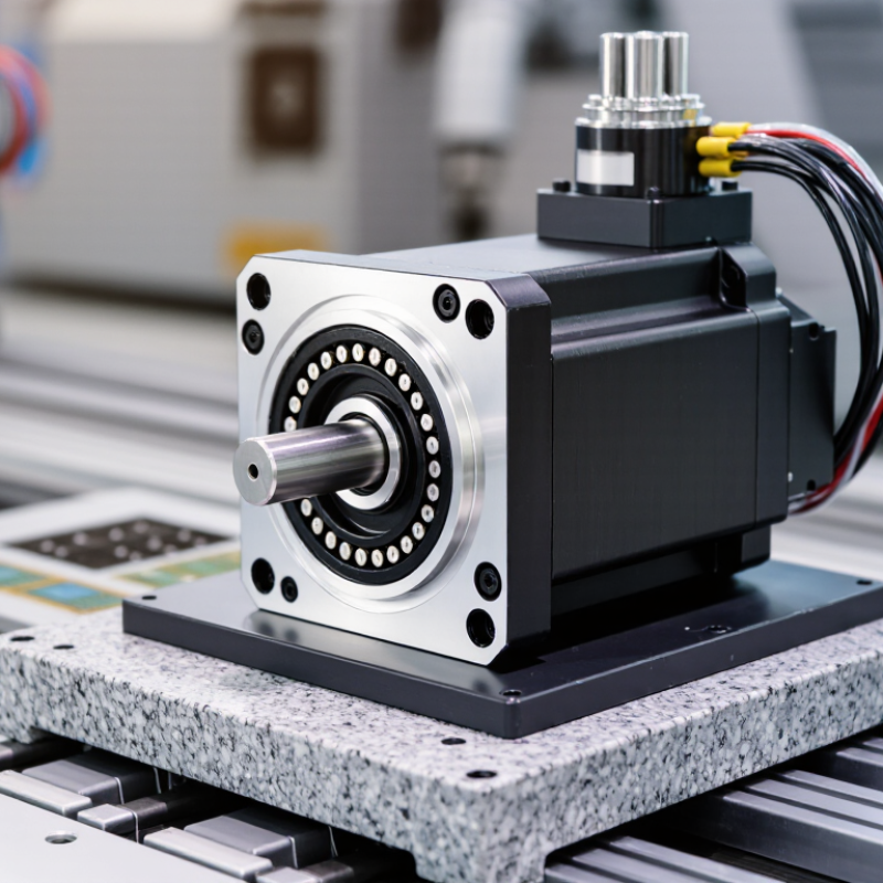
A direct drive linear motor converts electrical energy into straight-line motion without a screw, belt, gear, or other mechanical transmission. Its moving part travels directly along a guided path. The core principle is electromagnetic force. Current flows through coils, and their magnetic field interacts with permanent magnets. This interaction produces controlled thrust along the motor’s axis.
In practical testing, the motion feels immediate and clean. There is no visible backlash from a lead screw. The system can accelerate quickly, stop precisely, and reverse direction with little mechanical delay. A position encoder usually reports the mover’s location to a controller. The controller then adjusts current several thousand times per second, depending on the system design. Small alignment errors can still affect performance.
The term “frictionless” is tempting, but it is not fully accurate. Bearings, guides, seals, and air resistance still create losses. Heat also develops inside the coils, especially during continuous high-force operation. Engineers therefore check peak force, continuous force, duty cycle, payload, cooling, and guide stiffness before selecting a motor. A direct drive design may reduce maintenance, yet it does not remove every engineering problem. Careful tuning remains essential.
Key Components and How Linear Motion Is Generated
A direct drive linear motor creates straight-line motion without a screw, belt, or gearbox. Its key parts are a magnetic track, a coil assembly, position sensors, and a servo drive. The magnetic track supplies a fixed field. The coil assembly receives controlled three-phase current. Electromagnetic force then pushes the moving stage along the rail.
Motion begins when the drive changes current direction and strength. This creates a traveling magnetic force, similar to cutting a circular motor and laying it flat. A linear encoder measures position, often within micrometre-level resolution. The controller compares that reading with the target position and corrects current almost continuously. There is no mechanical transmission to stretch or wear. That is valuable in semiconductor tools, inspection systems, and high-speed packaging.
The market is expanding with factory automation. MarketsandMarkets estimated the global linear motor market at about USD 1.1 billion in 2023, with continued growth toward 2028. The International Federation of Robotics reported 541,302 industrial robots installed worldwide in 2023, showing the broader demand for precise motion systems. These figures do not measure direct drive motors alone, so comparisons need care. My practical concern is heat. Coil losses can distort the stage, even when the encoder reports excellent position. Designers therefore combine cooling channels, stiff guides, tuned servo loops, and careful acceleration limits. Fast is not always accurate.
Main Types and Structural Designs
What Is a Direct Drive Linear Motor? Main Types and Structural Designs
A direct drive linear motor converts electrical energy into straight-line motion without screws, belts, or gearboxes. Its stationary part creates a magnetic field, while the moving part carries the force. This structure reduces backlash and mechanical wear. It also supports rapid acceleration and precise positioning.
According to the International Federation of Robotics’ World Robotics 2024 report, 541,302 industrial robots were installed globally in 2023. That scale increases demand for compact, responsive motion systems.
The main designs include iron-core, ironless, tubular, and U-channel motors.
Iron-core motors generate strong thrust and suit heavy machining stages.
Ironless motors reduce cogging, which helps scanning and inspection equipment move smoothly.
Tubular motors place magnets inside a cylindrical track, saving space in sealed applications.
U-channel designs guide the mover between two magnetic tracks. They can improve stiffness, but alignment becomes critical. Small errors matter.
Single-sided motors are simpler and easier to install. Double-sided structures can balance magnetic forces and reduce bearing loads. Gantry systems combine multiple motors for wide platforms and synchronized movement.
In practice, thermal expansion remains a serious design issue. Heat changes accuracy. Cable routing can also limit speed, despite excellent motor specifications. A neat prototype may still perform poorly after continuous operation. Engineers should verify force, duty cycle, encoder resolution, cooling, and contamination resistance through measured tests, not catalog claims alone.
Performance Characteristics and Operating Advantages
What Is a Direct Drive Linear Motor?
Performance Characteristics and Operating Advantages
A direct drive linear motor converts electrical energy into straight-line motion without screws, belts, or gearboxes. Its moving part travels along a magnetic track, while feedback sensors measure position continuously. This shorter transmission path reduces backlash and mechanical wear. It also supports rapid acceleration, smooth velocity changes, and precise positioning in demanding automation equipment.
In practical operation, the motor can reach high speeds while maintaining quiet movement. It responds quickly because fewer mechanical parts absorb or delay force. Engineers often use it for inspection stages, semiconductor handling, laboratory equipment, and high-speed assembly. Repeatability remains strong when the guide system, encoder, and control loop are properly matched. However, the motor does not solve every design problem. Heat, cable movement, magnetic attraction, and guide alignment still require careful engineering. I have seen accuracy decline when thermal expansion was treated as a minor detail.
Tips: Select the motor from the required force, stroke, speed, and duty cycle. Check continuous and peak force separately. Leave thermal margin for warm environments. Use a suitable linear guide, because the motor does not support side loads by itself. Keep the feedback device clean and firmly mounted. A small alignment error can become visible at high speed. Tuning should begin with conservative acceleration settings, then progress through measured tests. Record position error, settling time, vibration, and motor temperature. Specifications are useful, but real machine behavior may differ.